Home >>Operating System Tutorial >Operating System I/O Hardware
Operating System I/O Hardware
Operating System I/O Hardware
An Operating System's essential job is to handle various I/O devices including a mouse, keyboard, touchpad, disc drives, monitor adapters, USB devices, bit-mapped screen, LED, an analog-to-digital converter, on/off switch, connections, audio I/O, printers, etc.
It takes an I/O system to take an I/O request for an application and send it to the physical device, then take any response from the device back and send it to the application. You can divide I/O devices into two categories.
- Block devices − One block device the driver communicates with by sending whole blocks of data. Hard disk, USB cameras, disk-on-key, etc., for example.
- Character devices − A character system is one that communicates with the driver by sending and receiving single characters (bytes, octets). Such as serial ports, parallel ports, sound cards, etc.
Device Controllers
Device drivers are software modules that can be plugged into an operating system to manage a specified device. Operating System is supported by device drivers in managing all I/O devices.
The Application Controller functions like a system-driver interface. Usually, I/O devices (keyboard, mouse, printer, etc.) consist of a mechanical component and an electronic component where the system controller is considered an electronic component.
Each computer has a device controller and a device driver to communicate with the Operating Systems. Multiple devices can be controlled by a system controller. As an interface, its main task is to convert serial bit stream to block bytes, perform as required error correction.
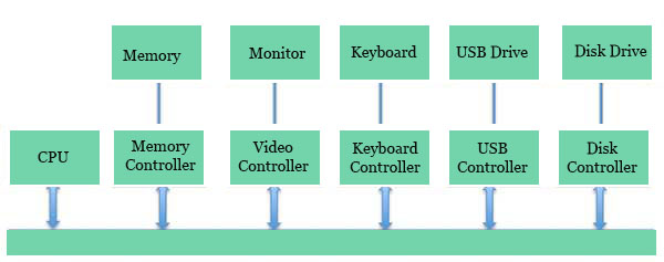
Any device connected to the computer is connected by a plug and socket, and a device controller is connected to the socket. A model for connecting the CPU, memory, controllers, and I/O devices follows, where both CPU and system controllers use a similar communication bus.
Synchronous vs asynchronous I/O
Synchronous I/O − CPU execution waits in this scheme as I/O goes
Asynchronous I/O − I/O runs at the same time as CPU execution
Communication to I/O Devices
The CPU must have a means of transferring information to and from an I/O device. There are three methods available for CPU and Device communications.
- Special Instruction I/O
- Memory-mapped I/O
- Direct memory access (DMA)
Special Instruction I/O
This uses CPU instructions specifically designed to controll I/O devices. Usually, these instructions allow data to be sent to an I / O device, or read from an I / O device.
Memory-mapped I/O
When using memory-mapped I/O, memory and I/O devices share the same address space. The device is directly connected to some main memory locations so that the I / O device can transfer data block to / from memory without having to go through the CPU.
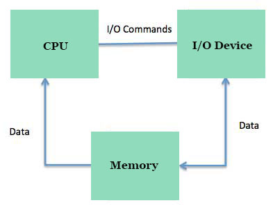
OS allocates buffer in memory by using memory mapped IO, and allows I/O devices to use the buffer to transfer data to the CPU. The system I / O runs asynchronously with the CPU, interrupts the CPU when it is complete.
The benefit of this approach is that an I/O device can be controlled for any instruction that can access memory. Memory mapped IO is used on most high-speed I / O devices, such as disk, interfaces for communication.
Direct Memory Access (DMA)
Slow devices such as keyboards can produce an interrupt to the main Processor after the transfer of each byte. If a quick device like a disks created an interrupt for each bit, the operating system will spend most of its time handling those interrupts. Therefore a typical computer uses hardware for direct memory access (DMA) to reduce the overhead.
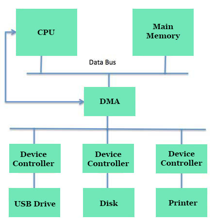
Direct Memory Access (DMA) means that CPU grants authority to read from or write to memory without involvement in the I / O module. DMA module manages data sharing between main memory and I / O device itself. Only at the beginning and end of the transfer is CPU involved and interrupted after the whole block has been moved.
Direct Memory Access requires a special hardware called DMA Controller (DMAC) which manages data transfers and arbitrates device bus access. The controllers are programmed with source and destination pointers (where to read / write the data), counters to monitor the number of transferred bytes, and settings for the CPU cycles including I / O and memory types, interrupts, and states.
The operating system uses the DMA hardware as follows −
| Step | Description |
|---|---|
| 1 | Device driver is directed to transfer data from disk to an X buffer. |
| 2 | Device driver then instructs disk controller to pass buffer data. |
| 3 | DMA transfer begins with the Disk Controller. |
| 4 | Byte is sent to DMA controller by disk controller. |
| 5 | DMA controller passes bytes to buffer, raises the address of the memory, decreases the counter C until C is zero. |
| 6 | As C becomes zero, DMA interrupts Processor for completion of the signal transfer. |
Polling vs Interrupts I/O
A computer must have a way to detect some sort of input going in. There are two ways this could happen, called polling and interrupting. Both of these techniques allow the processor to manage events that can occur at any time and are not connected to the process it is running at present.
Polling I/O
Polling is the easiest way to communicate with the processor via an I/O device. The process of checking the device's status periodically to see if it is time for the next I / O task, is called polling. The I / O system simply puts the information in a status log, and the processor has to come in and get the details.
Most of the time , devices won't need attention because when you do that you'll have to wait before the polling programme interrogates you next. This approach is inefficient and a lot of processing power is wasted on unnecessary polls.
Compare this approach to a teacher who regularly asks every student in a class if they need assistance, one after another. Obviously the more effective method will be for a student to tell the teacher if they need help.
Interrupts I/O
The interrupt-driven approach is an alternative scheme for handling I/O. An interrupt is a signal coming from a device requiring attention to the microprocessor.
A system controller places an interrupt signal on the bus when it needs the attention of the CPU when it receives an interrupt, saves its current state and invokes the necessary interrupt handler using the interrupt vector (OS routine addresses to handle different events). When dealing with the interrupting unit, the CPU goes on with its original task as though it had never been interrupted.